
SP-RO100/RO100MP 5- or 6-Stage Reverse Osmosis Filtration System
Installation and Instruction Manual

Important Note
For best results, please read through all instructions before beginning.
Parts Checklist

|
RO Manifold Head |

|
RO Membrane |

|
3 Pre-Filter Housings and Filter Cartridges |

|
3.2-gallon Water Storage Tank |

|
Air Gap RO Faucet (Sold Separately) |

|
Feed Water Adapter |

|
Color Tubing Set |

|
Drain Saddle |

|
Storage Tank Valve (2) 1/4" MPT x 1/4" Quick Connect Inlet & Outlet Fittings |

|
Housing Wrenches |

|
Leak Stop Valve (Sold Separately) |

|
Spare O-rings, Fittings, and Teflon Tape (package quantity may vary) |
Tool List
We recommend having the following tools on hand to help with the installation process:

|
Utility Knife |

|
Phillips Screwdriver |

|
Adjustable Wrench |

|
Variable Speed Electric Drill |

|
3/8" Drill Bit for Drain Saddle |

|
Bucket |

|
Cloths |

|
1/8" Diamond-Tip Drill Bit (if installation requires faucet opening) |

|
1" Diamond-Tip Drill Bit Hole Saw (if installation requires faucet opening) |
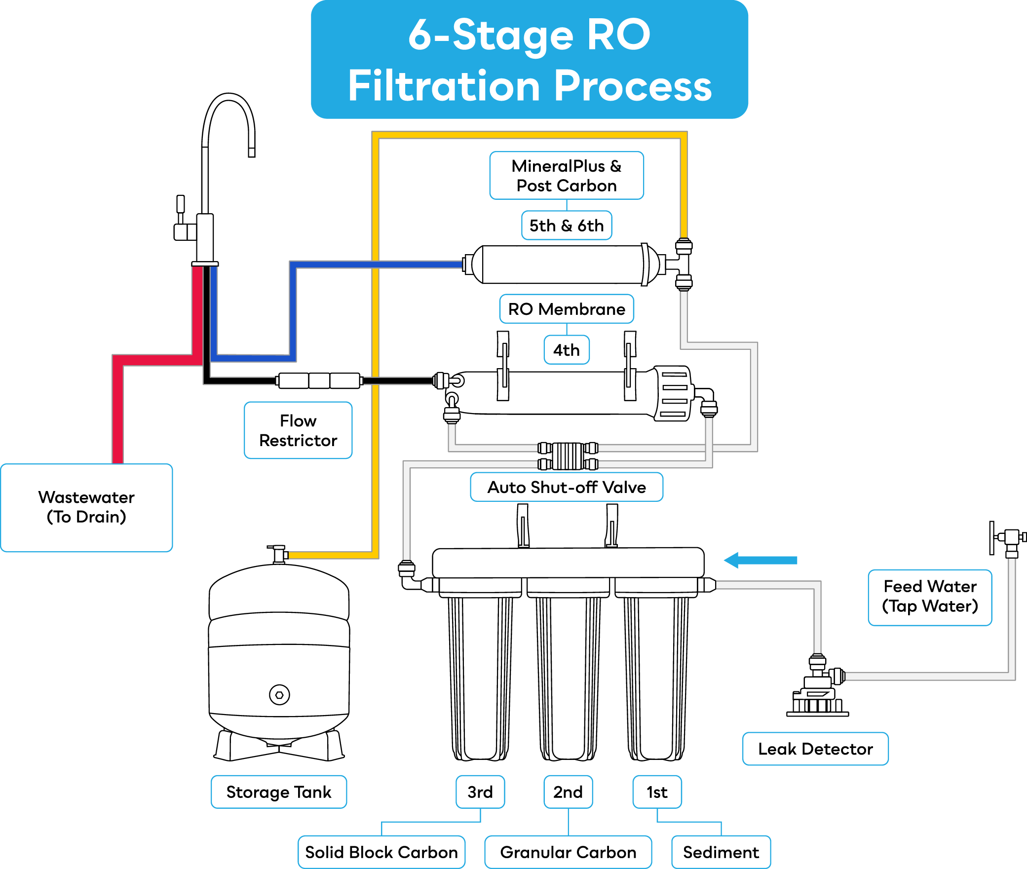
Advanced 6-Stage RO Filtration Process
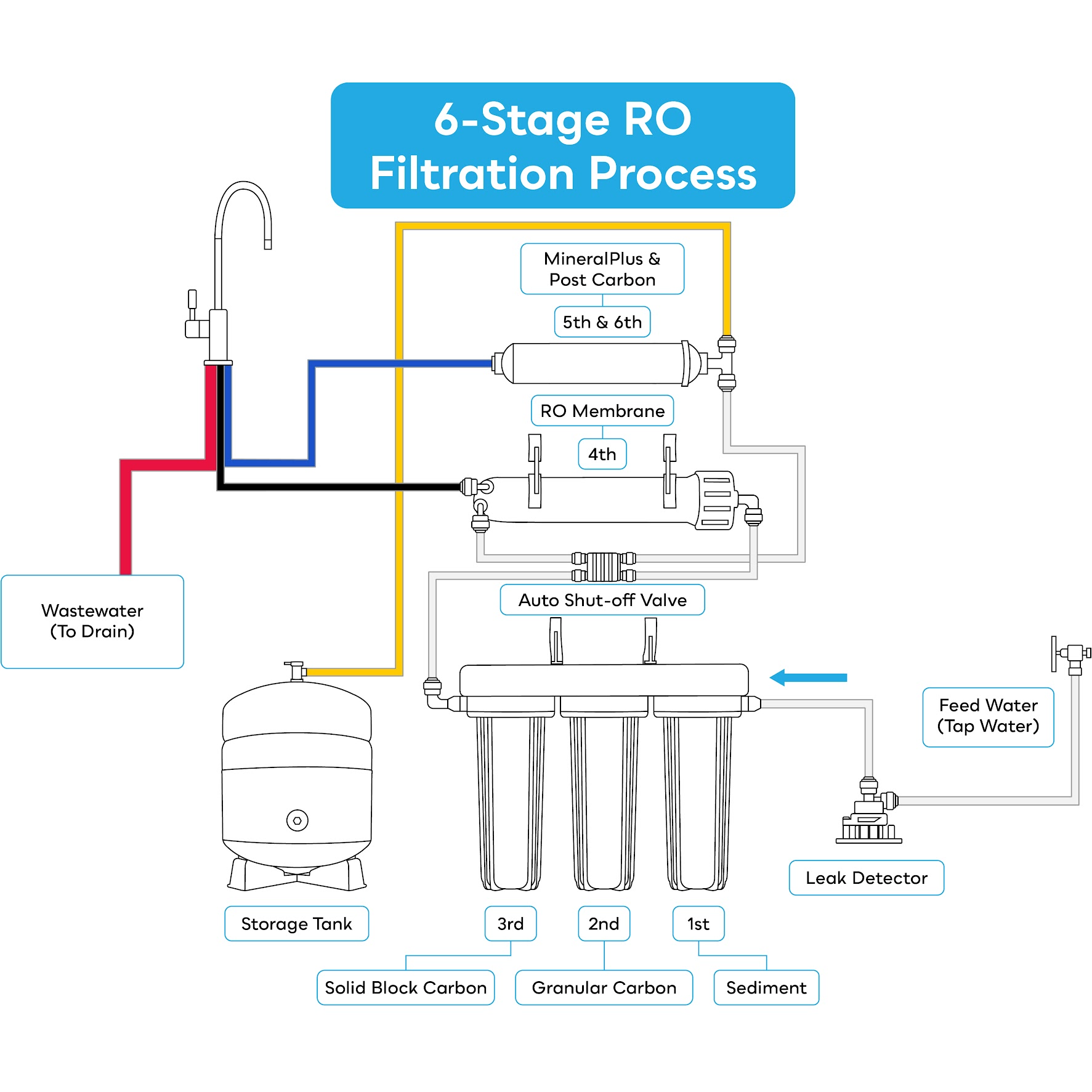
| Stage | Description | Filter Life |
|---|---|---|
| 1 | SP-AP110 Sediment Filter | 12 months |
| 2 | SP-GAC-10R GAC Filter | 12 months |
| 3 | SP-CBC-10 Solid Block Carbon Filter | 12 months |
| 4 | SP-RO-075R RO Membrane | 12 months |
| 5–6 | SP-ROPC MineralPlus and Polishing Carbon Filter | 12 months |
Elite 6-Stage Filtration
- 10x2.5 Sediment Cartridge: Our grooved melt-blown polypropylene media captures sediment, rust, and other dirt particles to help protect and extend the life of the RO membrane and system.
- 10x2.5 GAC Carbon Cartridge: Our GAC (granular activated carbon) made from coconut shell reduces chlorine, taste, odor, and cloudiness from water.
- 10x2.5 Carbon Block Cartridge: Our solid carbon block cartridge uses NSF certified coconut shell PAC (powder activated carbon) that further improves taste while also reducing unwanted contaminants such as chloramines and chemicals.
- 75 GPD (Gallons Per Day) RO Membrane: Offers a polyamide thin-film composite membrane that filters water down to 0.0001 micron in size to reduce more than 1000 impurities.
- MineralPlus and Post Carbon: A dual-stage final post-remineralizer and carbon rinse refreshes the treated water, taking care of residual taste or odor from the RO membrane or mineral media.
Installation Options
Both the SpiroPure FC100 and FC210 RO Water Filter Faucets feature an optional air gap feature to work with your undersink drinking water filter system, including RO and non-RO systems.
The use of the air gap feature on SpiroPure faucets is optional and does not have to be used. The air gap, however, is built in and cannot be removed. (Note: because the optional air gap cannot be removed, the faucet will require a minimum 3/4" hole and ideally a 7/8" hole to fit more comfortably.)
*Important note: An RO air gap is louder due to air gurgling through the system while the water tank fills. An air gap is required in RO system installations by many US plumbing codes to prevent brine waste from the RO process from mixing with the filtered water. Check your local plumbing codes.
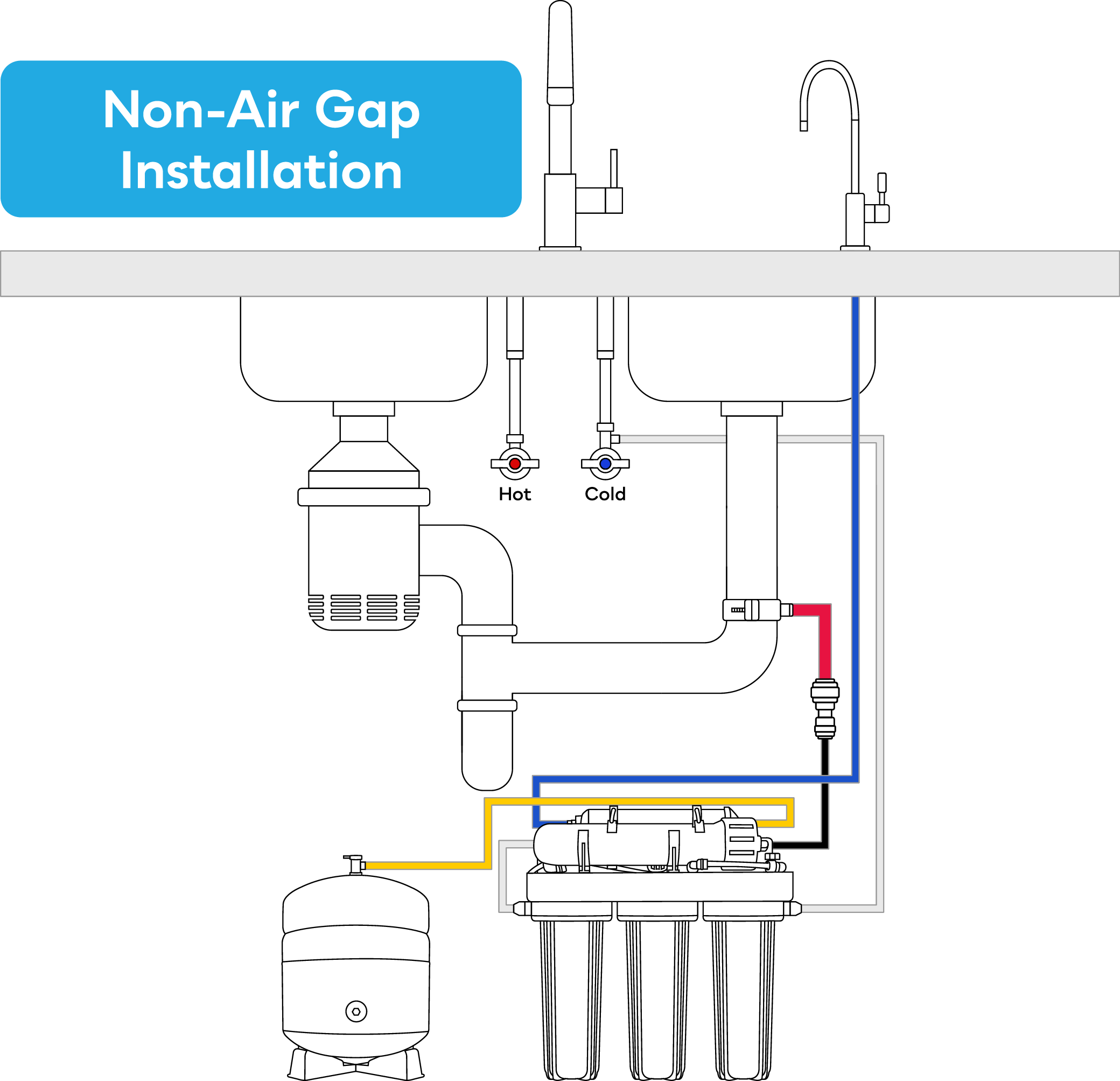
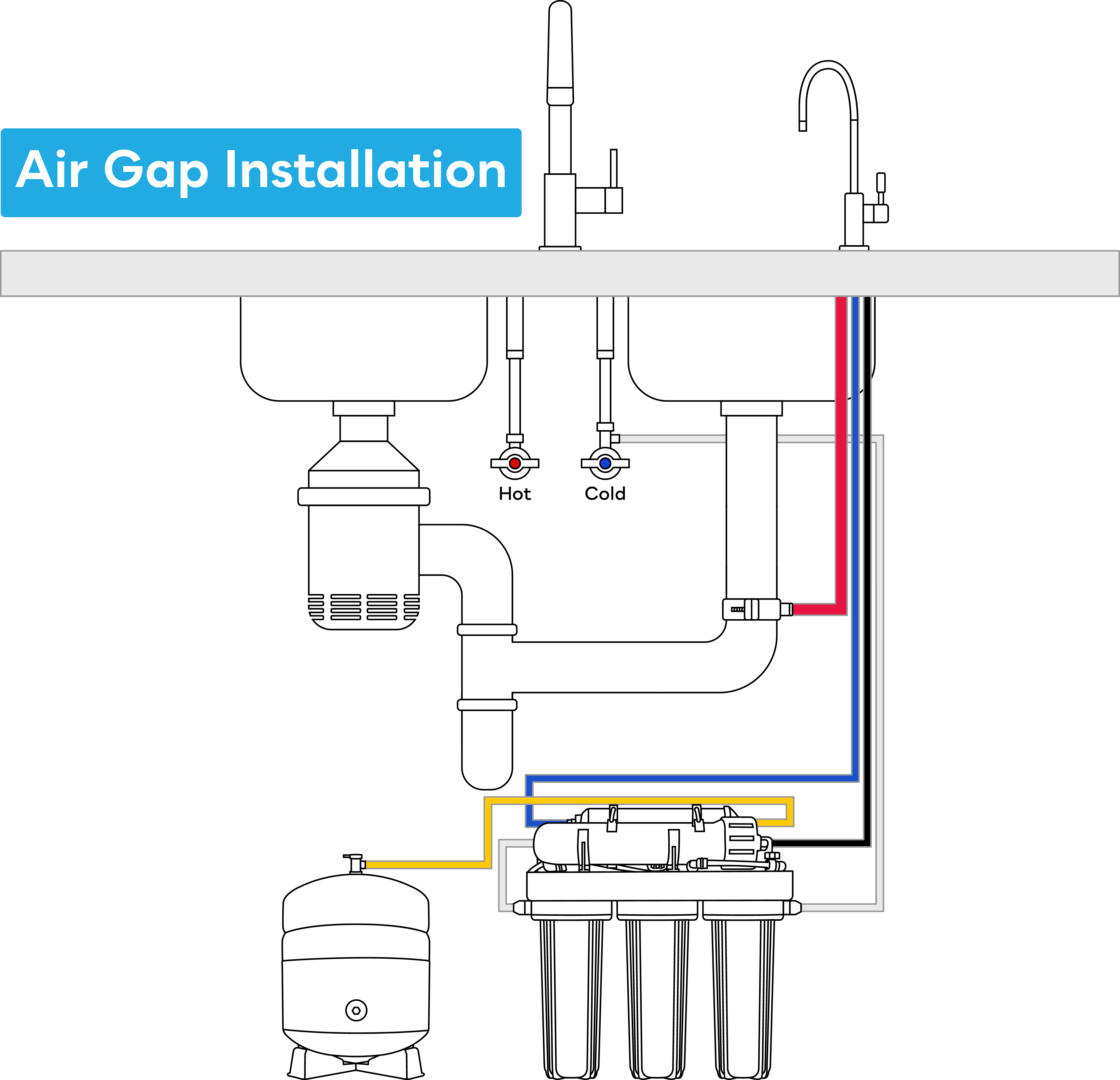
Use the color-coded tube connections to complete the installation more easily:
| Connection | Tube Color | Description |
|---|---|---|
| Air Gap Faucet | Blue | Polished water to the faucet |
| Feed Water Valve | White | Tap water to the RO system inlet |
| Tank Valve | Yellow | Filtered water to storage tank |
| Membrane Waste Connector | Black | Membrane waste to 1/4" air gap faucet inlet |
| Air Gap Faucet Outlet | Red | 3/8" air gap faucet outlet to drain saddle |
Preparing for Installation
Determine the location for the RO system, RO faucet, and water storage tank.
- The faucet can be installed in a pre-drilled hole on the sink, if available. If drilling a new hole, make sure not to damage any plumbing or wiring that may be under the countertop or sink. (Drilling may require a qualified professional. See Faucet Installation for more details.)
- The pressure storage tank can stand upright or be laid on its side.
- The storage tank and RO faucet can be up to 5 feet apart. If the tank needs to be farther away than 5 feet, we recommend a booster pump to supply adequate pressure at the faucet.
Tubing Connection Tips
| Insert Tubing | Release Tubing | ||
|---|---|---|---|
|

|


Installation Instructions
Warnings:
- This system is for cold water supplies only. Do NOT install the system on the hot water supply line. Hot water will damage the system.
- Installation and use must comply with all state and local plumbing codes.
- This system is for indoor use only.
- A pressure regulator is required if incoming water pressure is over 80 psi. Note: optimal home water pressure is typically 40–75 psi.
- It is highly recommended to shut off the water supply to the system unit when it will not be in use for longer than a week.
- Do not use with water that is microbiologically unsafe or of unknown quality without adequate disinfection before or after the system.
Prepping RO:
- Remove all components from the box. Using the Parts Checklist, verify that all of the parts are included. Once all parts have been verified, continue on to step 2.
- Remove the filter cartridges from the filter housings and unwrap. Insert the filter cartridges into the filter housings.
Important Note: The stage 1 and stage 3 filters are bi-directional, and can be inserted with either end leading. The stage 2 filter (SP-GAC-10R) has a clear plastic lip on one end—this plastic lip should be facing up, into the filter housing.

- Ensure the O-rings on the filter housings are seated properly in the grooves.
Important Note: Filter cartridges must go in a specific order:
- Stage 1 (SP-AP110)
- Stage 2 (SP-GAC-10R)
- Stage 3 (SP-CBC-10)
Hand tighten the filter housings back onto the RO system in a clockwise direction. Use the filter wrench to tighten filter housing 1/4 turn, or until it is snug. Do not overtighten the filter housings.
*Once your RO system is in service, if a filter housing is leaking, use the filter housing wrench to tighten. Do not overtighten the filter housings. Overtightening may damage the O-ring(s), cause water leaks, or affect overall system performance.
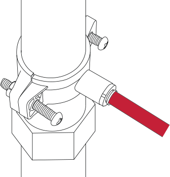
- Disconnect the tubing from the fitting on the 4th stage RO membrane housing cap.*

- Remove the end cap from the housing by turning it counterclockwise as shown below:

- Insert the RO membrane cartridge into the housing. Ensure that the O-rings on the water tube of the cartridge are fully seated in the membrane housing (the cartridge will be seated flush with the housing). Make sure that the brine seal on the membrane seals without gaps or wrinkles inside of the housing.

- Make sure the O-rings on the housing and in the housing cap are properly seated. Replace the housing end cap, using the housing wrench to tighten. Do not overtighten.
- Reconnect the tubing, using the push fitting to insert it back into the membrane housing cap.
*Important Note: It is strongly recommended that you flush the Stage 1-3 pre-filters separately from the RO membrane. During startup, you'll flush the system for about 10 minutes and discard all water prior to connecting the RO membrane. Also see "Replacing Filter Cartridges” for detailed instructions on bypassing the RO membrane.
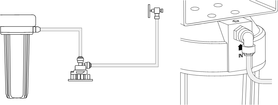
Feed Water Adapter Installation
Attention: The water supply line to the system must be from the cold water supply line only. Hot water will severely damage your system. Use the provided metal adapters to fit the feed water adapter to your existing water line.
- Turn off the cold water supply to the faucet by turning the angle stop valve completely off.
- Open the cold water sink faucet to relieve pressure from the water line.
- Prior to disconnecting the faucet connector, lay down a bowl or bucket to catch any water drips. Unscrew the kitchen faucet connector pipe from the cold water supply valve.
- Ensure the O-ring is seated inside the feed water adapter on the female end, using provided metal adapters as required, and connect it to the cold water supply. Tighten using a wrench or pliers.
- Check that the O-ring in the kitchen faucet connector pipe is still properly seated. Connect the kitchen faucet connector pipe onto the male end of the feed water adapter, using provided metal adapter as needed, and tightening with a wrench or pliers.
- Remove the blue locking clip from the feed water adapter. Insert the 1/4" white tubing that goes to the reverse osmosis system. Reinsert the locking clip.


Faucet Installation
Note: Some sinks have pre-drilled 1" holes that are suitable for installation of your Drinking Water faucet. If your sink has such a hole, skip to the faucet installation instructions.
Notice: Please refer to recommendations from the countertop or sink manufacturer or a professional for drilling a hole in a countertop or sink. The RO system manufacturer and supplier do not accept any responsibility for damage resulting from installing faucets in any surface, including but not limited to granite, marble, or porcelain sinks.
Recommendation for granite or marble countertops, porcelain sinks, and other surfaces: ALWAYS use a qualified professional for drilling a hole because these materials can crack and chip easily during the process.
- Gather and identify the faucet pieces from the faucet parts bag and system parts bag.
- Start by sliding the escutcheon onto the bottom of the faucet, lining up the holes on the base plate with the 3 inlet/outlet port stems on the faucet. The escutcheon has the rubber O-ring preinstalled.
- (Air Gap Installation Only) Before mounting the faucet, install the waste water tubing on the faucet. The 1/4” blue filtered water tubing is already connected for convenience. First, push the 1/4" black wastewater tube onto the smaller, 1/4" air gap barb fitting at the bottom of the faucet, making sure to push it at least 1/2" up the fitting.
- (Air Gap Installation Only) Push the 3/8" red wastewater tube onto the 3/8" air gap barb fitting at the bottom of the faucet, making sure to push it at least 1/2" up the fitting.
- Insert the tubing (blue for Non-Air Gap Installation or blue, red, and black for Air Gap Installation) and the stem through the pre-drilled hole.
- From the underside of the sink, slide on the slotted metal washer, spacer, star washer, washer, and mounting nut.
- Check the orientation of the faucet, then tighten the locking nut securely with a wrench. Do not overtighten fittings.
- (Optional) Install the spacer if the countertop is less than 1/2" thick (e.g., a stainless steel sink). You do not need a spacer if your countertop thickness is 1/2" or more.
- Connect the 1/4” blue filtered water hose to the outlet on the RO membrane.
- (Air Gap Installation Only) Connect the other end of the 1/4" wastewater line to the RO system’s wastewater output port.
- (Air Gap Installation Only) Connect the other end of the 3/8" wastewater line to the drain saddle. See below for instructions on how to mount the drain saddle.
- Flush the faucet with water and check for leaks.
SP-FC100 Faucet Installation Instructions

- (Air Gap Installation Only) Before mounting the faucet, install the water tubing on the faucet. Begin by pushing the 1/4" wastewater tube onto the smaller, 1/4" barb fitting at the bottom of the faucet, making sure to push it at least 1/2" up the fitting.
- (Air Gap Installation Only) Push the 3/8" wastewater tube onto the 3/8" barb fitting at the bottom of the faucet, making sure to push it at least 1/2" up the fitting.
- Slide the escutcheon base of the faucet up over the water lines, and insert it into the bottom of the body of the faucet.
- Insert the faucet lines and stem into the hole on the countertop or sink. For the next few steps, it may be easier if you have a second person hold the faucet in position above the counter.
- Underneath the counter, insert the black rubber washer in the proper position over the water lines and faucet stem, making sure to line up the pieces with the hole on the washer.
- Slide on the metal washer against the rubber washer and then slide up the plastic spacer. It may be easier to try and mount both pieces simultaneously.
- Screw the black lock washer wing nut onto the threaded faucet stem under the metal washer or optional spacer, making sure to tighten but not overtighten.
- Depending upon the size of your undersink water filter’s filtered water hose, screw the 1/4" or 3/8" union adapter onto the end of the threaded faucet stem. Be sure to tighten but not overtighten.
- Connect the filtered water hose from the undersink water filter system to the union adapter.
- (Air Gap Installation Only) Connect the other end of the 1/4" wastewater line to the RO system’s wastewater output port.
- (Air Gap Installation Only) Connect the other end of the 3/8" wastewater line to the drain saddle.
- Flush the faucet with water and check for leaks.
SP-FC210 Faucet Installation Instructions

Mounting the Drain Saddle
Warning: The drain saddle creates a wastewater connection with the sink drain and is designed to fit a standard 1-1/2" OD drain pipe. Drain saddles should always be installed at least 1-1/2" above the nut of the p-trap on a vertical or horizontal drain. Do not install near a garbage disposal. Take extreme caution to only drill through one side of the drain pipe.

- Locate a spot at least 1-1/2" above the nut of the p-trap on the drain pipe that is convenient for installing the drain saddle. It is recommended to install on horizontal piping to minimize dripping noise.

- The small, square, black foam gasket with a circle cut out of the middle must be applied to the inside of the drain saddle. Remove the backing and stick to the drain saddle as shown.

- Using the 3/8" drill bit, drill into only one side of the drain pipe. Do Not drill through both sides of the pipe.
- Assemble the drain saddle around the drain pipe and align the opening with the hole drilled in the previous step. You may use a small screwdriver to feed through the drain saddle hole to aid with the alignment.

- Measure the 3/8" red tube from the faucet to the drain saddle on the drain pipe and make a straight cut to the correct length.
Notice: The red 3/8" drain tube to the drain saddle must be as SHORT and STRAIGHT as possible. Make sure there is a downward slope from the faucet to the drain saddle to allow for proper drainage without causing the tube to stretch or sag.
Tips:
- If tubing is looped, it can cause water to come out of the air gap faucet.
- Looped tubing can shorten the life expectancy of the RO membrane.

Installing the Storage Tank Valve
Warning: Do not adjust the air valve on the storage tank. It has been preset to 8-10 psi by the manufacturer.
- Remove the plastic stand at the top of the tank.
- Use the Teflon tape to wrap the 3/8" fitting at the top of the tank 6 times.
- Place the storage tank on its stand in the desired location, and position either horizontally or vertically.

- Insert the yellow tubing from the 5th stage (Post Carbon Inline Filter) into the storage tank valve, about 1/2" deep (see the Advanced 5-Stage RO Filtration Process diagram for reference).
- Turn off the storage tank valve.

Installing the Leak Stop Valve (Optional)
Note: When the leak stop valve detects a leak, it will automatically shut off the inlet water to the RO system, protecting your home from potential water damage.
Warning: The valve is highly sensitive to water. Please install with caution, as the leak stop pad easily absorbs water and will require replacement every time it comes into contact with water.
- Find a dry, flat surface next to the RO system to place the leak stop valve.
- Use the screws or double-sided tape to mount the leak detector to the cabinet floor or screw the leak detector into one of the six designated locations in the optional leak tray (SP-LD200-KIT SP-LD152-TRAY)

- Measure from the feed water adapter to the leak detector inlet and cut the 1/4" white inlet tubing.
- Connect the tubing from the feed water valve to the inlet port of the leak stop valve.
- Measure from the outlet of the leak detector to the 1st stage pre-filter housing.
- Connect the 1/4" white tubing from the outlet port of the leak stop valve to the inlet port on the 1st stage sediment pre-filter housing.
Starting the System
Important: For each phase of starting the system, ensure correct tubing has been properly connected. Check that all of the connections are secure before turning on the water supply. If using, the leak stop pad should be installed after initial system startup. This is to ensure the pad does not need to be replaced during startup due to tubing that is not inserted properly or a loose housing. Refer to the checklist on the next page and diagram below:
Pre-filter Flush
- Disconnect the white tubing from the system outlet port fitting on the manifold by the stage 3 (Solid Block PAC Carbon) filter housing.
- Disconnect the 1/4" black tubing from the wastewater port by the RO membrane.
- Connect the 1/4" black tubing to the outlet port fitting on the manifold.
- Turn on the cold water supply valve and slowly turn on the feed water adapter valve.
- Let the water fill the pre-filter housings and flush the cartridges for about 10 minutes. Black wastewater tube can also be drained into a bucket. Flush until the water turns clear.
- Shut off the feed water adapter valve and cold water supply valve.
- Disconnect the 1/4" black tubing from the system outlet port fitting.
- Reconnect the 1/4" black tubing to the wastewater port by the RO membrane.
- Reconnect the tubing from the RO membrane housing back to the system outlet port fitting.
Check All Connections
- The blue faucet tubing connects to the 5th stage post-carbon inline filter.
- The white water-supply feed tubing connects to the 1st stage sediment cartridge housing.
- The yellow storage tank tubing connects to the 5th stage post-carbon inline filter at the union tee fitting.
- The 1/4" black wastewater tubing from the RO faucet connects to the RO membrane.
- The 3/8" red wastewater tubing from the RO faucet connects to the drain saddle.
Start Up the System
- Close the storage tank valve.
- Slowly turn on the cold water supply and the undersink adapter valve. If leaks are present, turn off the cold water supply valve and correct the problem before proceeding.
- Open the gray flush valve for 3 minutes to purge RO membrane. Close flush when completed.

- Turn on the RO faucet to release any air from the system.
- After several minutes, water will begin to drip or trickle from the RO faucet.
- Let it trickle for approximately 10 minutes, then turn off the RO faucet.
- Turn on the storage tank valve. It will take 1 to 3 hours for the storage tank to fill, depending on your home’s water pressure. You will know the tank is full when you hear the water stop running to the drain pipe.
- After the tank is full, flush the system by turning on the RO faucet until the water in the tank is completely discharged. Discharge takes around 3–5 minutes.
- After the tank is emptied, turn off the RO faucet and allow the tank to refill. Refilling will usually take 1 to 3 hours.
- Turn on the RO faucet and allow the tank to flush once more.
- Turn off the RO faucet and allow another 1 to 3 hours for the tank to refill.
- Once you have determined the RO system has no leaks, close the feed water adapter valve, open the leak detector drawer, and install the cartridge/pad. Close the leak detector drawer and open the feed water adapter valve.

- After the tank has refilled for a third time, you can begin to enjoy your clean, freshly filtered water.
Warning: Do NOT drink the first tank of water produced by the system. We recommend refilling and flushing the tank twice before use.
Check daily for leaks during the first week of use. Check for leaks periodically after the first week.
Water may be milky or cloudy during the first week of use. This is caused by air bubbles in the water and is normal. The water is completely safe to drink and use.
Tubing Connection Checklist
| Feed Water Adapter | Drain Saddle |
|---|---|

|
|
| Feed Water Valve Line to Stage 1 (Sediment Housing) of RO system | |
|
|
| Stage 3 (Carbon Block Housing) | Shut-off Valve |

|

|
| Stage 4 (RO Membrane Housing) | Wastewater Line & Flow Restrictor (RO Membrane Housing) |

|

|
| Yellow water line to storage tank & white water line to RO membrane housing | Blue filtered water faucet tubing & 1/4" black wastewater line & 3/8" red wastewater line |

|

|
Recommended Maintenance
To help your system achieve maximum efficiency and service life, perform the recommended maintenance procedures in the sections that follow.
Note: This RO system utilizes filter cartridges that must be periodically replaced to maintain system performance. Frequency of changes may vary depending upon water quality.
Filter Replacement Set
| SP-RO125MP | One Year Filter Replacement Set for SP-RO100 RO Systems |
|---|---|

|
|
| Stage | Description | Filter Life |
|---|---|---|
| 1 | SP-AP110 Sediment Filter | 6 months |
| 2 | SP-GAC-10R GAC Filter | 6 months |
| 3 | SP-CBC-10 Solid Block Carbon Filter | 6 months |
| 4 | SP-RO-075R RO Membrane | 12 months |
| 5–6 | SP-ROPC MineralPlus and Polishing Carbon Filter | 12 months |
- Filters may be stored for several years. See note in the next section about storing RO membrane cartridges.
- Store unopened, sealed filters in an airtight container to extend shelf life and protect from unwanted odor.
Membrane Cartridges
- Dry-packed RO membrane cartridges typically have a one-year shelf life. To extend shelf life, keep the unopened, sealed membrane element in a refrigerator.
- After the first use, run the RO system every day for 10-15 minutes to maintain membrane performance.
- If the RO system will not be used for several weeks, drain the storage tank completely. Open the gray flush valve for 3 minutes to purge the RO membrane. Be sure to fill and drain the tank 2 times before using the system again after a period of non-use.
Replacing Filter Cartridges
- Use a drip pan or similar container to catch any water that may spill when the filter housing is removed. When replacing all filters at the same time, follow the steps in Replacing Filter Cartridges and Replacing RO Membrane Cartridges, below, then flush and refill the tank twice as recommended.
- Turn off the feed water supply valve and the cold water supply valve.
- Turn off the storage tank valve.
- Turn on the RO faucet to release any pressure and water still in the lines.
- Open the leak detector drawer and remove the lead stop pad. Close the leak detector drawer.
- Unscrew the filter housings.
- Remove and discard the old filter cartridges.
- Unwrap and install the new filter cartridges, making sure to install them in the proper order of Stage 1: SP-AP110 Sediment Filter, Stage 2: SP-GAC-10R GAC Filter, and Stage 3: SP-CBC-10 Solid Block Carbon Filter.
- Make sure the O-rings are properly seated in the housing.
- Screw the housings back onto the manifold clockwise.
- Tighten the housings with the included housing wrench, making sure to tighten without over-tightening to avoid damaging the O-rings.
- Disconnect the white tubing from the system outlet port fitting on the manifold by the stage 3 (Solid Block PAC Carbon) filter housing.
- Disconnect the 1/4" black tubing from the wastewater port by the RO membrane.
- Connect the 1/4" black tubing to the outlet port fitting on the manifold.
- Turn on the cold water supply valve and slowly turn on the feed water adapter valve.
- Let the water fill the pre-filter housings and flush the cartridges for at least 5 minutes.
- Shut off the feed water adapter valve and cold water supply valve.
- Disconnect the 1/4" black tubing from the system outlet port fitting.
- Reconnect the 1/4" black tubing to the wastewater port by the RO membrane.
- Reconnect the tubing from the RO membrane housing back to the system outlet port fitting.
- Turn on the cold water supply valve and feedwater supply valve and check for leaks.
- If there are no leaks, ensure the area is dry. Open the leak detector drawer and install the cartridge/pad. Close the leak detector drawer.
Note: If the housing is difficult to unscrew, try unplugging the fitting or tubing to release air and water pressure inside the housing.
Warning: Do NOT drink the first tank of water produced by the system without flushing the newly installed filters. We recommend refilling and flushing the tank twice before use if you choose not to flush the pre-filters separately from the RO membrane.
Replacing RO Membrane Cartridges
- Ensure cold water supply is turned off. Disconnect the white tubing from the RO membrane cap and proceed to unscrew the cap of the RO membrane Cartridge housing.
- Slide out the used RO membrane and discard.
- Unwrap and insert the new RO membrane cartridge, with the two O-ring side entering the housing first. Be sure the cartridge is fully seated in the housing. Refer to the diagram:

- Screw the cap back onto the RO membrane housing, ensuring that the O-ring is still in place. Re-insert the white tubing into the RO membrane cap. Turn on the cold water supply.
- Open the flush valve for 3 minutes to purge the RO membrane. Close the flush valve when completed.
- It may take 10-20 minutes for flow rate to return to normal after installation of the new membrane.
- When flow rate has returned to normal, turn on the storage tank valve. After 1 minute, turn off the RO faucet.
- Warning: Do NOT drink the first tank of water produced by the system. We recommend refilling and flushing the tank twice before use.
System Cleaning
Note: We recommend performing the following cleaning procedures for the system and tank when changing the filters, every 12 months.
- Shut off the water supply to the RO system.
- Open the RO faucet to depressurize the RO system and storage tank.
- Remove the filter cartridges, post-filter cartridges, and RO membrane cartridge. Discard and prepare for cleaning. (Note: The water supply in some households may benefit from changing pre-filters every six months and membranes themselves may last longer than a year. In either case, if the RO membrane will stay in use, place the RO in a clean, sanitary place during system cleaning.)
- Wash the internal housing areas with warm, soapy water and a brush or sponge. Do not scratch the surfaces.
- Remove the O-rings and replace or clean. Make sure to clean O-ring grooves on housings thoroughly.
- Rinse off housings with clean water.
- Replace O-rings and lubricate according to the O-ring manufacturer specifications.
- Leaving the filters out, replace the Stage 2 and 3 empty filter housings by hand tightening them onto the unit. Measure and pour 1/4 cup of common household bleach into the first filter housing (Stage 1) and hand tighten onto the unit. Homeowners with septic systems should avoid bleach and use a commercially available sanitizer such as "Sani-System" or other cleaner to avoid killing beneficial bacteria.
- With the RO faucet in the closed position, turn on the incoming water supply to the system. Let the unit fill with water (approximately 8 minutes), allowing the bleach to dilute.
- Let the system sit idle for 1 minute and turn off the incoming water supply.
- Drain the system completely by opening the RO faucet. Close the RO faucet once the system is completely drained.
- Open the angle stop. Let the system fill again (approximately 8 minutes) and sit idle 10 minutes before draining the system again.
- Turn off the incoming water at the feed water adapter valve and open the faucet to make sure all the water has been drained.
- Open the RO membrane housing and reinstall the RO membrane. Refer to Replacing Membrane Cartridge tab for direction on installing the RO membrane.
- Remove the filter housings for Stages 1, 2, and 3 and empty the water.
- Insert the new cartridges for Stages 1, 2, and 3. Then screw housings back onto the RO manifold.
- Make sure the storage tank is empty. Check the pre-charge pressure with a pressure gauge (a car's tire gauge should work). The average empty tank pressure should be 8-10 psi.
- Follow the start-up instructions under the Starting the System tab.
- Keep a maintenance record for the RO system that includes information such as replacement parts, services performed and dates, and service providers.
Troubleshooting
Warning: Turn off the system before servicing or inspection.
| Problem | Possible Sources | Solution |
|---|---|---|
| Milky Water | Air bubbles in the system | This is a normal occurrence upon system startup. The milky color will disappear with normal use in one to two weeks. |
| Faucet Noise |
|
|
| Lack of Water Flow from Faucet |
|
|
| System not Draining | Clogged flow restrictor | Replace the flow restrictor. |
| System Leaks |
|
|
Warranty
SpiroPure warrants that the water filtration system delivered will be free from any defects in workmanship or materials. If your SpiroPure water filtration system fails because of a manufacturing defect within one (1) year from the date of the original purchase, SpiroPure will exchange the defective water filtration system for a new SpiroPure water filtration system without charge.
SpiroPure's obligation to the customer under these warranties shall be limited, at its option, to replacement of items covered by these warranties.
Damage to any part of this system because of misuse, misapplication, negligence, alteration, accident, installation, or operation contrary to our instructions, incompatibility with accessories not installed by SpiroPure, or damage caused by freezing, flood, fire, or Acts of God are not covered by this warranty. In all such cases, regular charges will apply. This limited warranty does not include service to diagnose a claimed malfunction in this unit. This warranty is void if the claimer is not the original purchaser of the unit or if the unit is not operated under normal municipal water or well water conditions.
We assume no warranty liability in connection with this system other than that specified herein. This warranty is in lieu of all other warranties, expressed or implied, including warranties of fitness for a particular purpose. SpiroPure’s liability hereunder shall not exceed the cost of the product. Under no circumstances will SpiroPure be liable for any incidental or consequential damages or for any other loss, damage, or expense of any kind, including loss of use arising in connection with the installation or use or inability to use the covered items. These warranties may change at any time without notice.
Some states do not allow limitations on how long an implied warranty lasts, and some states do not allow the exclusion or limitation of incidental or consequential damages. Therefore, the above limitations may not apply to you. This Limited Warranty gives you specific legal rights, and you may have other rights that vary from state to state. You should consult applicable state laws to determine your rights. So far as is consistent with implied warranties of merchantability and fitness for a particular purpose, the warranties are limited in duration to one (1) year from the date of original shipment.